As the dummy block presses the billet through the container, oxide and impurities become trapped at the end of the billet. It is crucial to eliminate these residues in the dead metal zone before loading the next billet. Utilizing a properly-designed shear blade helps eliminate the blister, reduce surface contaminates, provide consistency in extrusion, and increase the production rate.
Too often the shear blade is not given sufficient attention in terms of design, use and maintenance. Design considerations are necessary depending on the alloy and butt lengths typically in use on the press, and blade type changes may be necessary at product changes.
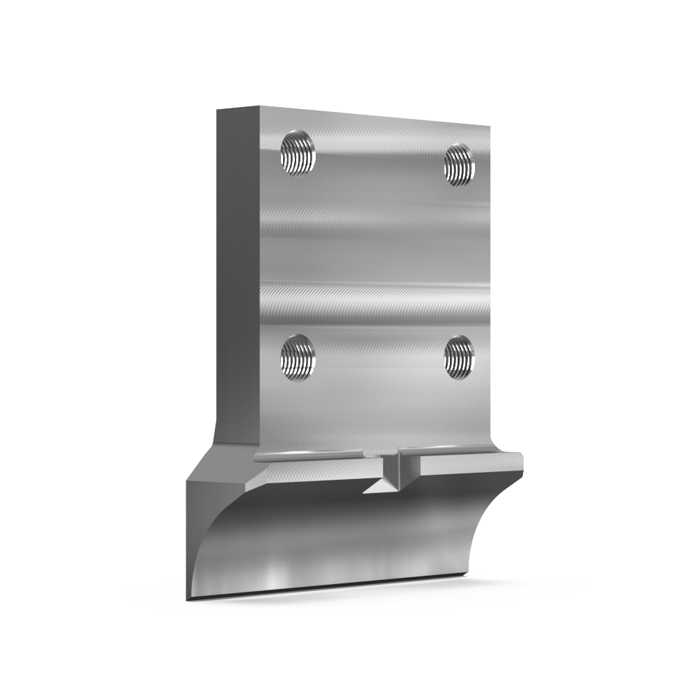
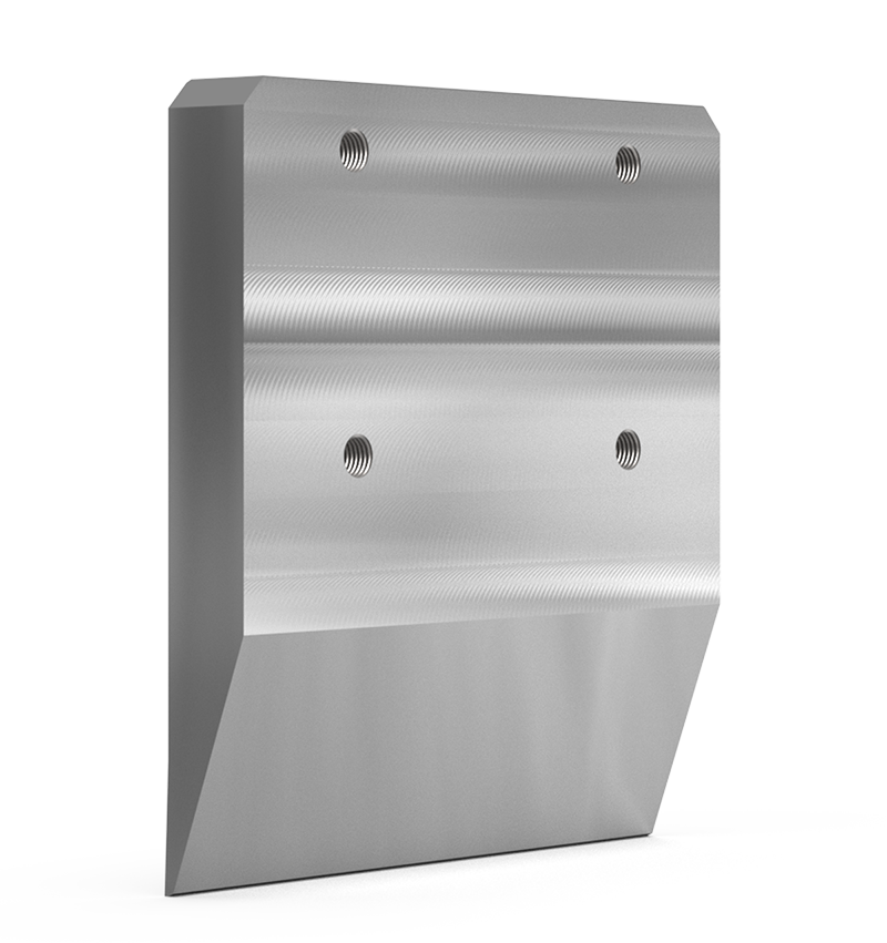
In the case of softer 6xxx alloy extrusion, the cut and curl type blade needs to be provided with a sharp edge and a scooped rear face to enable effective butt removal. Damage to the cutting edge of the design may cause the butt to stick to the blade, or cause failure of the blade itself. Chips and cracks on the cutting edge may indicate inadequate blade clearance and impact with the die or die ring.
As with any cutting blade the clearance between the shear blade and die face needs to be controlled. Lubrication of the rear face of the blade encourages flow of the butt across the blade, and helps butt detachment. Shear blade lubrication practices are effective, but lubricant must not be applied to the front face to ensure lubricant does not contaminate the die face and create extrusion problems such as blister and possible seam weld failures.
Shear blades should be removed from the press at frequent intervals and inspected and replaced if necessary.
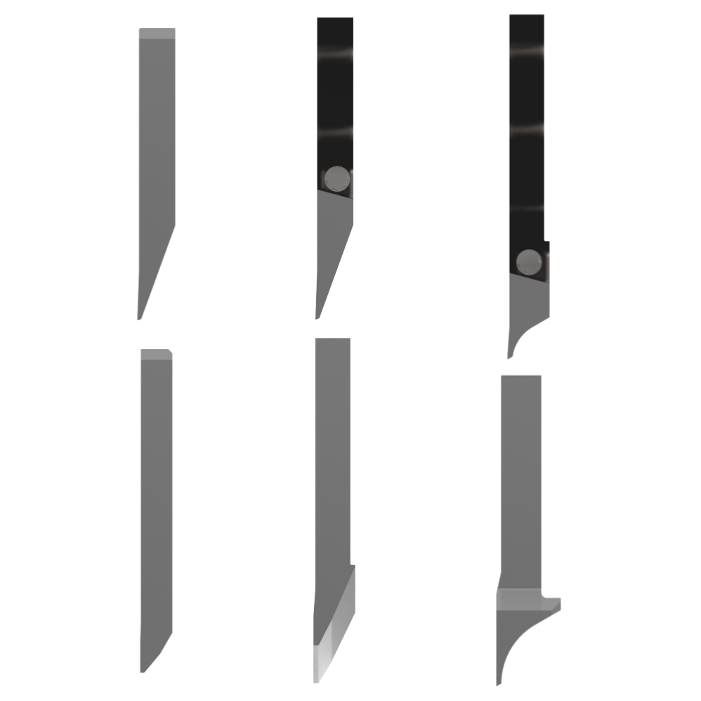
- The knife blade is the most effective geometry, but requires good extrusion practices.
- The 2-piece design allow the cutting edge to be changed on the press and can be adapted to all blade types.
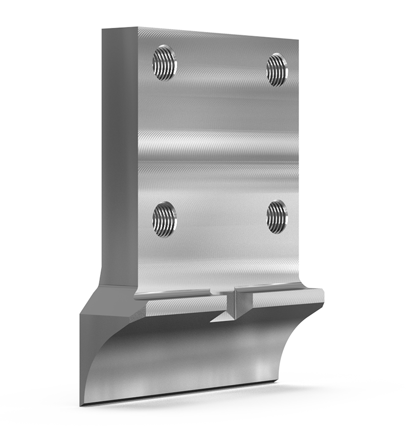
- Soft alloy (typical butt length 20-35 mm).
- This shear blade provides a “cut and curl” action and behaves as a knife blade, to cut through the butt/die interface.
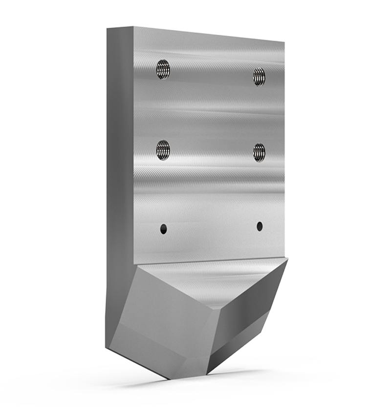
- Medium alloy (typical butt length 30-60 mm)
- This shear blade provides a “cut and split” action to cut through the butt/die interface
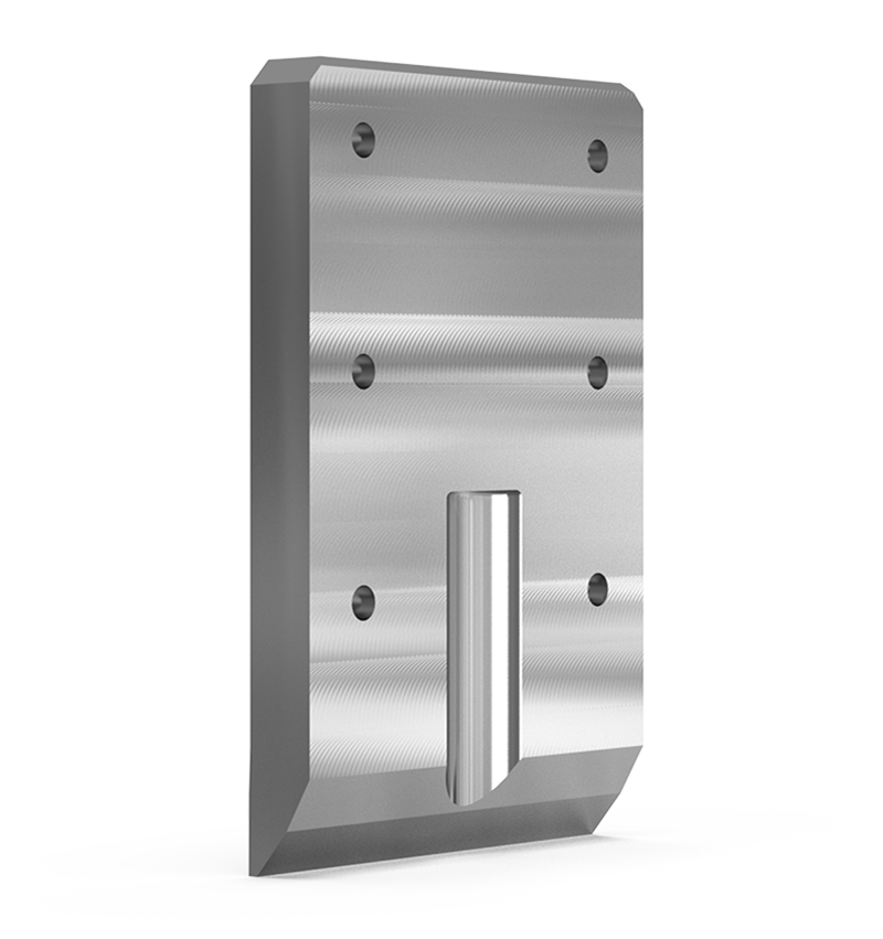
- Hard alloy (typical butt length longer than 60 mm).
- This shear blade behaves as a shear, rather than a knife, and shears through the butt/die interface.
►The clearance between the shear blade and die/die ring is critical to ensure the butt is effectively removed without pull out from ports and pockets and without undue smearing onto the die/container sealing surfaces. For cut and curl type blades this clearance shall be controlled to be within 1 mm maximum range. The target shear blade clearance shall be 0.6 mm.
► Shear blade clearance shall be checked under hot operating conditions, or set under cool conditions (on installation of a new blade during maintenance downtime periods), by using a setting device adjusted to accommodate temperature differences. Note: after installation of a new shear blade under cool conditions, allow the blade and tooling to stabilize to typical extrusion conditions before start up by sealing the container to a die stack with the shear blade above.
► Shear blade clearance will be influenced by :
- Toolstack overall length variation
- Wear of the die slide guideways (both bottom and rear)
- Distortion in the die cassette and/or damage to the cassette horseshoe
- Wear of the shear column guideways
- No, or ineffective, clampdown of the die ring prior to butt shear
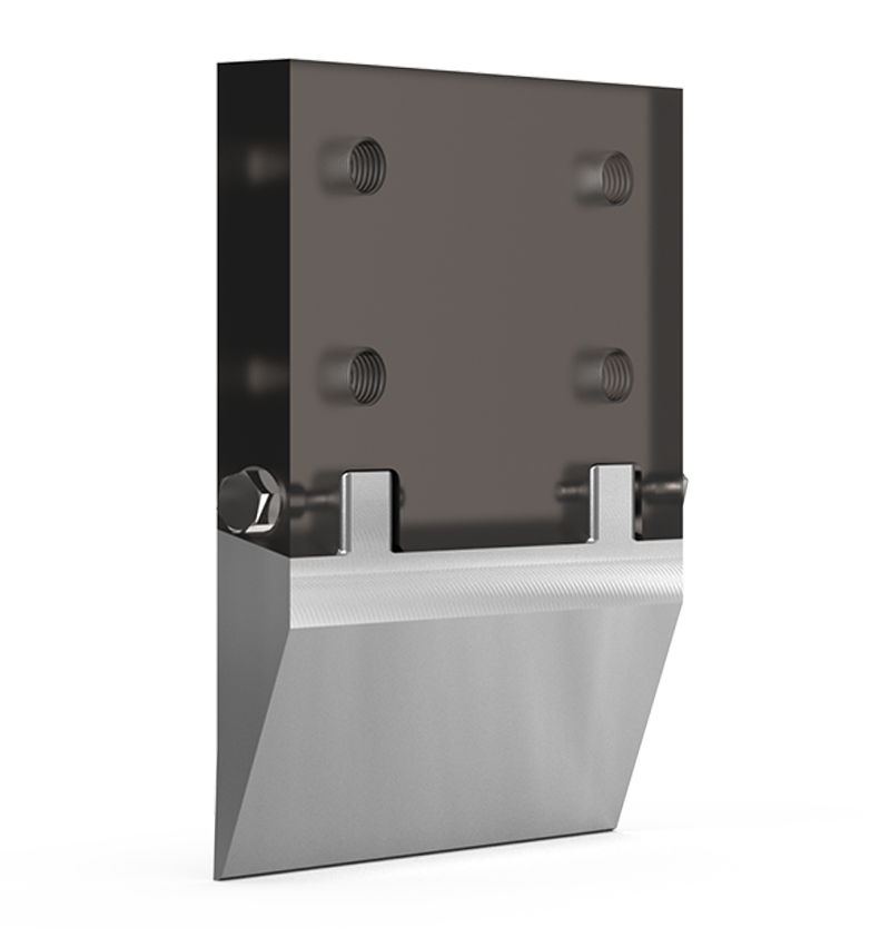
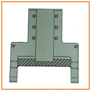
► Shear blade clearance can be controlled with shear blade design incorporating guidance fingers to ensure the die face and shear blade face maintain the same separation during butt shear travel (see diagram).
► Shear blade clearance can also be controlled with a die stack, or die cassette clamping system that ensures constant clearance control. The device pulls the die stack (or die ring) against the register of the horseshoe in the cassette, or against the platen. This former eliminates variation in die stack length due to stack up of tolerances in the lengths of die stack components. If no such device is available, then improved control of die stack component lengths (dies, backers, bolsters and sub bolsters) is necessary.
► Vertical movement, and to a limited extent, axial movement can be restricted with the use of a vertical die ring clamp.
Purpose
- To separate extrusion butt which contain oxides and impurities
Function
- To eliminate blister due to pull out from die ports and feeder from die.
- To eliminate extrusion flaring due to smearing of alloy across die face.
- Specific blade design for soft, medium and hard alloys.